How To Select A Die Spring
Century Spring offers die springs in both oil-tempered and chrome-alloy. Die springs are used primarily in die machinery, but are also well-suited for applications where high- or shock-load stresses are required or when maximum cycle-life is important. To order, shop stock die springs online or request a quote for custom springs.
Selecting A Die Spring
If the application is for a die set, always use as many springs as the die will accommodate to produce the required load and cause the least amount of deflection. This will increase the service-life and reduce the chances of early failure.
Decide if the springs will be used for short or long runs, average or high-frequency cycling, or high stress in order to select the duty-level capability found in the following pages of inventory.
The higher the rate of cycling, the higher the rate of fatigue-caused failures. In slow-oscillating dies or fixtures, it is possible to get good performance with springs operating near maximum deflection. As the working speed increases, the life expectancy of the spring at that deflection decreases.
NOTE: The suggested maximum deflections are expressed as percentages of free length. These guideline limits are important for extended service life.
Rate Charts
Rate - Pounds Per Inch of Deflection
This chart indicates how the load-carrying capability of the die spring increases by scanning through the color code range of the 3" long spring’s increasing duty capability.
| Hole Size | Rod Size | Free Length | LD (Blue) | MD (Red) | HD (Gold) | XHD (Green) |
|---|---|---|---|---|---|---|
| 3/8" | 3/16" | 3" | 18 | 30 | 42 | 65 |
| 1/2" | 9/32" | 3" | 40 | 57 | 74 | 90 |
| 5/8" | 11/32" | 3" | 56 | 100 | 144 | 180 |
| 3/4" | 3/8" | 3" | 96 | 144 | 312 | 405 |
| 1" | 1/2" | 3" | 152 | 232 | 54 | 736 |
| 1-1/4" | 5/8" | 3" | 240 | 512 | 95 | 1184 |
| 1-1/2" | 3/4" | 3" | 336 | 624 | 122 | 2312 |
| 2" | 1" | 3" | 768 | 960 | 185 | 3120 |
Cycle Life & Maximum Deflection
| LD (Blue) | MD (Red) | HD (Gold) | XHD (Green) | |
|---|---|---|---|---|
| High Cycle Life Range % of Length | 25% to 35% | 20% to 25% | 15% to 20% | 15% |
| Suggested Maximum Deflection % of Length | 50% | 37% | 30% | 25% |
Die Spring Characteristics
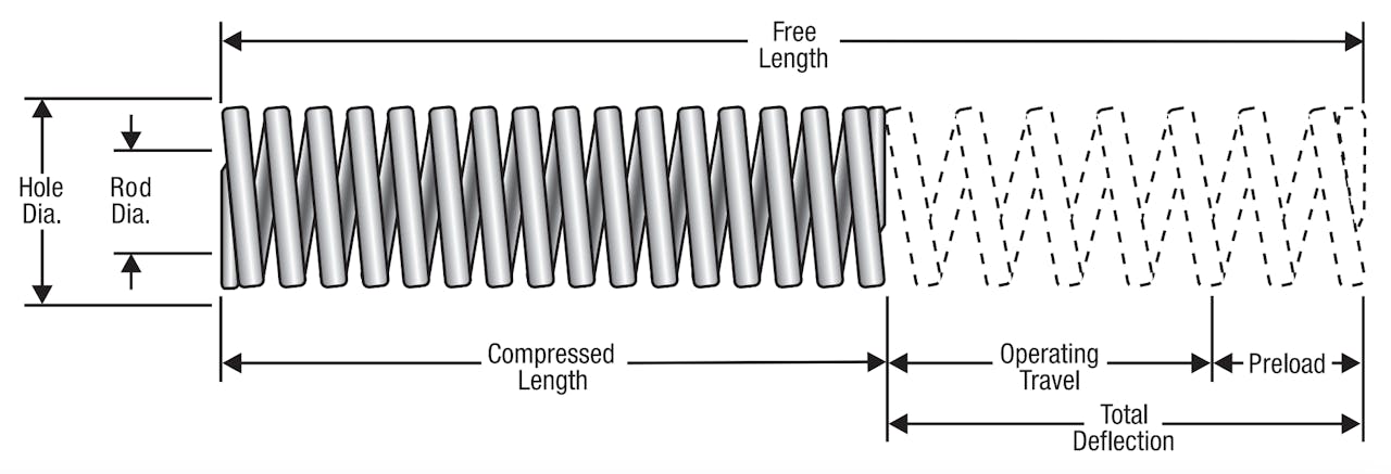
Holes and Rod Diameter
The die spring containment hole diameter sizes tabulated in the following pages of inventory must be considered to eliminate possible spring-to-wall friction caused by heat, wear due to fabrication tolerances, and interference from the spring diameter growth due to compression. If the spring is long for its diameter, an internal supporting rod may be required to eliminate spring buckling.
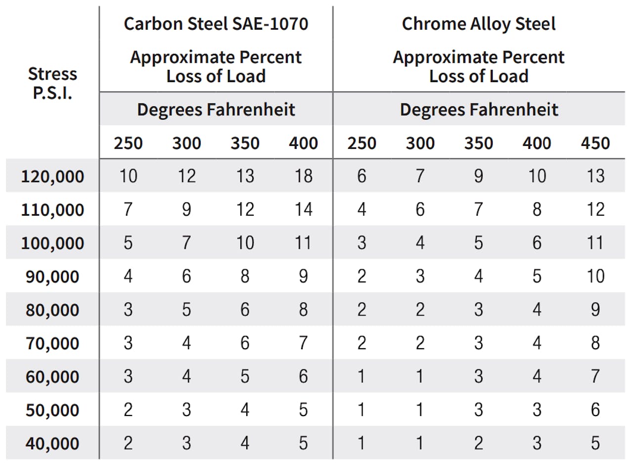
Heat
Thermal effects are frequently ignored in spring failure or loadloss analysis. The maximum rated service temperature for chrome-alloy steel is about 440° F. The following table reflects the approximate load losses due to heat that can be expected with die springs.
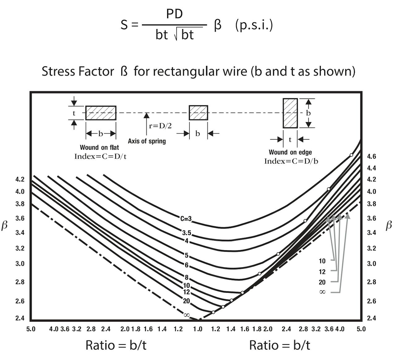
Stress Determination
The die wire stress can be estimated with the rectangular wire equation on the right, where:
P = Load, lbs.
D = Mean coil diameter, (O.D. - d) inches
b = Wire width (radially), inches
t = Wire thickness, inches
β = Stress-correction factor, see below
Material and Load Loss Due to Temperature
All of our die springs are fabricated from the most efficient wire cross section, which is rectangular with rounded corners. The oil- tempered die springs are offered for die sets and general use at a reduced cost. A very long service life may be expected from oil- tempered springs if their maximum deflection is held to about 25 percent of their length. The highest grade of electrically-furnaced, shot- peened and preset chromealloy steel die springs are offered for unsurpassed quality
The chart on the right shows the approximate percent of load loss at different temperatures for die springs made from carbon steel and chrome alloy steel.
Die Spring Finishes
Die springs of oil-tempered material are available as unfinished only. A color coding system is employed for our chrome-alloy line for instant visual identification of the spring’s work range and to prevent errors in spring selection and installation. The color coding is a light coating of water-based paint.
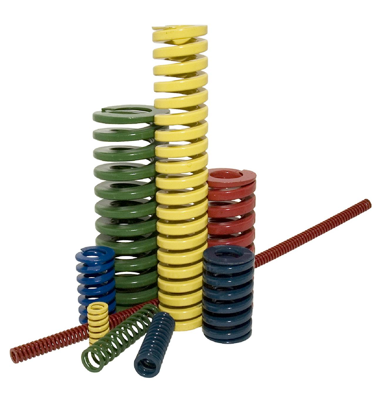
Chrome Alloy Finishes
| Color | Range |
|---|---|
| Blue | Light Duty |
| Red | Medium Duty |
| Gold | Heavy Duty |
| Green | Extra-Heavy Duty |
Chrome Silicon Finishes
| Color | Range |
|---|---|
| Green | Light Load |
| Blue | Medium Load |
| Red | Heavy Load |
| Yellow | Extra-Heavy Load |
Contact Us
For further design and engineering resources, visit the Century Spring resource center or for specific questions related to our products or services, contact us.